
Training a Unitree G1 on ground rebuilt from the same three-drone clip as the motion raised no-fall runs from 128 to 196 of 200 in simulation. From an 11.6-second markerless capture, we reconstructed the ground as a 5 cm heightfield with no LiDAR, survey or markers. A drone left out of the reconstruction agrees with it to about 10 mm at the median (a flat plane: 44 mm). The analysed section drops about 0.2 m over 16 m, so a flat floor is wrong by several centimetres at most steps. A Unitree G1 policy trained only on flat ground stayed up in 128 of 200 randomised MuJoCo runs on the rebuilt path; fine-tuned on the rebuilt terrain plus procedural terrain, it stayed up in 196. With terrain heights doubled the gap was 43 against 185. All robot results are in simulation.
01The capture
On October 10, 2026 we filmed a person at Baylands with three drones. In the clip used here they walk along a dirt path and break into a jog. Our pipeline already turns footage like this into a 3D body for every frame, retargets it to a Unitree G1 humanoid and trains a policy that tracks it. Until now that robot always stood on a flat floor. The real path is not flat, and we wanted to know whether the difference shows up in the robot.
Nothing extra was recorded for the ground. The terrain comes from the same video, camera poses and timing as the body, so the ground and the person share one world frame and one clock.
02Rebuilding the ground
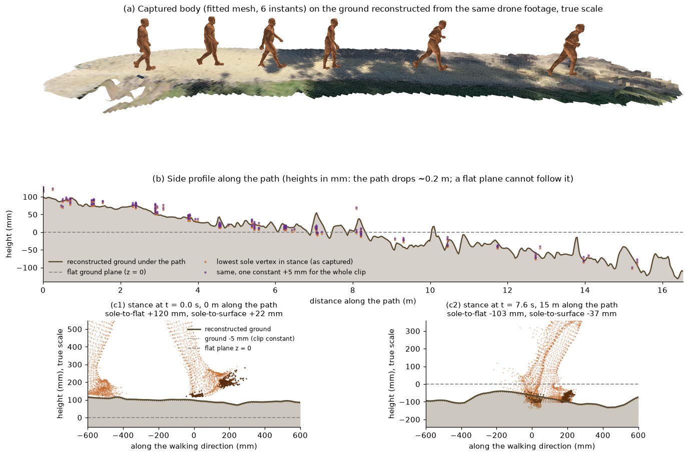
We split the area around the path into 5 cm cells and, for each cell, tried a range of heights. At each height we projected a small ground patch into about 240 drone frames and scored how well the views agree. Where the person stands in a frame, we project the body mesh and mask it out so a leg is not mistaken for ground. A second pass uses tilted patches, then a robust smoothing step fills small gaps and gives each cell a confidence. This is plain multi-view geometry, with no learned model, and takes about 20 seconds on a GPU for roughly 42,000 cells.
03How we checked it
There is no survey of this path, so we used three checks that do not depend on the method grading itself.
| Check | Rebuilt ground | Flat plane |
|---|---|---|
| Held-out drone: best height seen by a drone left out of the reconstruction, distance to the surface (median) | 10 mm | 44 mm |
| Held-out drone: image shift when its view is predicted from the surface (median) | 1.5 px | 7.0 px |
| Cells where the surface explains the held-out view better than the plane | 79% | |
| Sparse structure-from-motion points from the camera solve, signed distance to the surface (median) | −3 mm | |
| Surface from two drones vs from all three (median difference) | 2.7 mm |
The held-out check rebuilds the ground from two drones and asks the third which height looks right at each cell. The 10 mm median equals the step size of the height search, so it is at the resolution of the test. The structure-from-motion points come from the camera solve itself and only set the starting range of the height search, so they are a consistency check rather than an independent one; the surface still sits within a few millimetres of them with no systematic lift, including under the feet. Metric scale comes from the person’s known height (1.83 m), so absolute heights can be off by a few percent. The flat plane is our earlier ground reference, set from the person’s own ankle height and the overall tilt of the scene.
04The feet against the ground
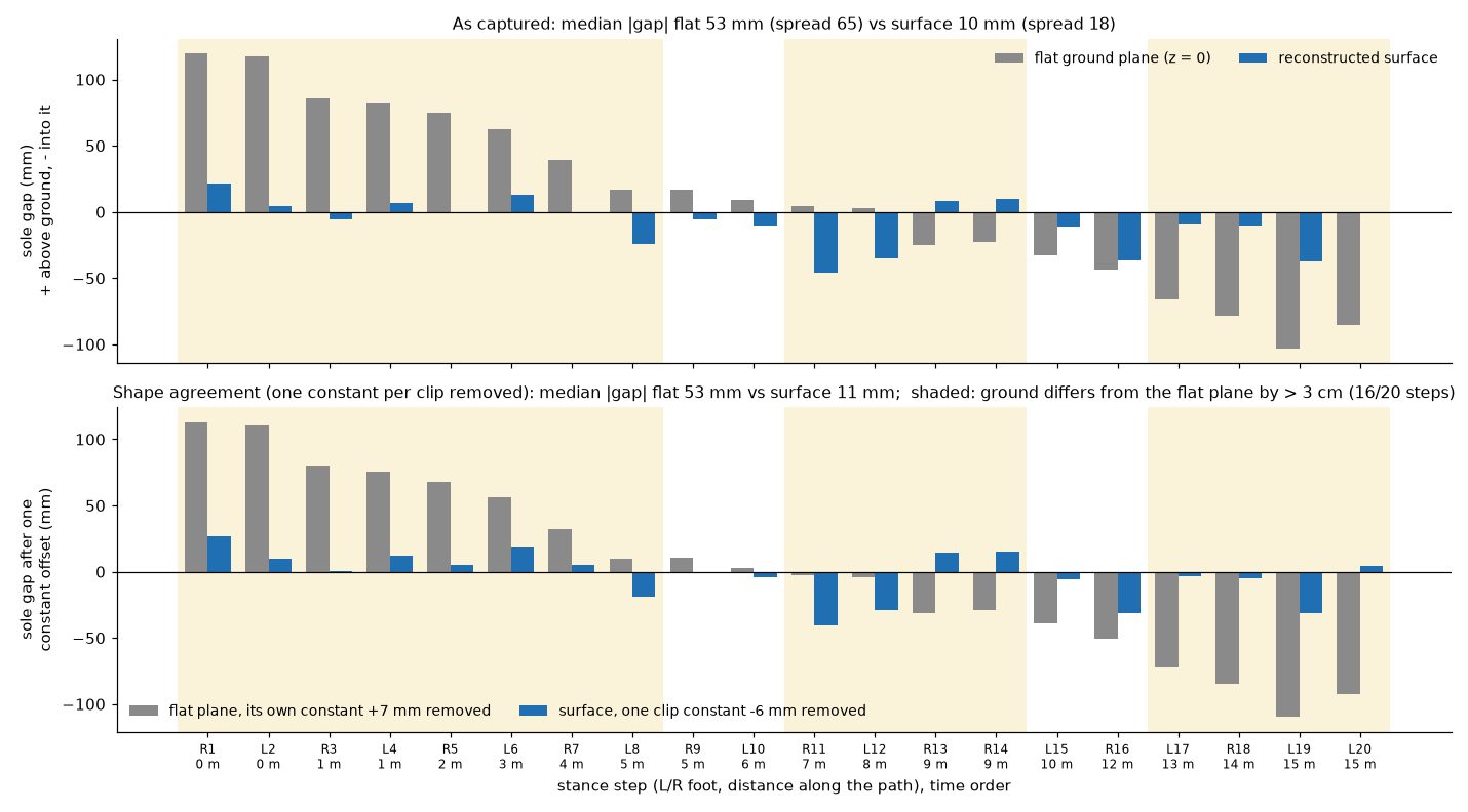
For each of the 20 stance steps in the clip we measured the gap between the sole and the ground under it. Our first version found a constant: the fitted body mesh’s soles sat about 27 mm below the rebuilt ground along the whole path and for both feet.
The ground did not cause it: the structure-from-motion points gave the same offset, and the triangulated ankle sat at the right height above the surface. The cause was our silhouette refinement step. Seen from above by the drones, a point just under the sole falls inside the shoe’s outline in every view, so nothing stopped the soles growing downward. We now constrain foot vertices from going below the fitted foot and fail the step if a sole moves more than 10 mm; the same fix removes the offset on two other takes. The numbers below are with the fix, as delivered, with no per-clip correction.
| Per stance step (19 steps) | Rebuilt ground | Flat plane |
|---|---|---|
| Median gap (20 steps) | 10 mm | 53 mm |
| 90th percentile gap | 37 mm | 105 mm |
| Steps within 5 cm | 100% | 50% |
| Spread from step to step | 18 mm | 65 mm |
The rebuilt ground matches where the feet actually landed to 10 mm at the median, and the sole height follows the surface height step by step (r = 0.96). The flat plane cannot be fixed with one constant, because the error changes sign along the path: the person starts about 8 cm above it and ends about 8 cm below it.
05A flat-trained policy on the rebuilt path (simulation)
Next we put the G1 on the rebuilt path in MuJoCo, using a tracking policy we had trained on a flat floor for this clip. Each condition is one nominal run and 200 randomised ones with the same seeds across conditions: floor friction, mass and inertia, motor gains, up to 20 ms of command delay, sensor noise, start noise and pushes every 1–3 seconds. A run succeeds if the robot does not fall during the 11.6-second clip. The policy is blind: it sees its own body state and the motion it should track, not the ground.
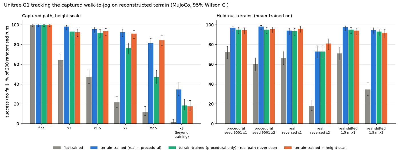
On a flat floor this policy stays up in all 200 runs. On the rebuilt path it stays up in 84 when it follows the motion as captured over flat ground, and in 128 when the whole body of the reference is first shifted up and down to follow the ground under the pelvis (averaged over 0.4 m and 0.3 s; step-sized bumps are left to the policy). Per seed, 60 runs succeed only with the adjusted reference and 16 only without (sign test p = 4 × 10⁻⁷). We use 128 as the flat-trained baseline from here on: the terrain-trained policy follows the same adjusted reference, so this comparison isolates the training, and it is the one less favourable to us. Scaling the terrain heights up as a stress test, with the adjusted motion, drops it further: 95 at 1.5 times the captured heights, 43 at twice, 3 at three times.
06Training on the terrain
We fine-tuned the flat policy for 3,000 iterations of PPO with 4,096 parallel environments in MuJoCo-Warp, which took about 58 minutes on one shared GPU. Each episode drew a terrain tile: the rebuilt path at 0.5 to 2.5 times its heights (45% of episodes), procedural terrain with the same bumpiness as the real path (45%), or flat ground (10%). The policy stayed blind. We evaluated in standard CPU MuJoCo with the same 200 seeds, on the path itself and on terrains the policy never saw in training: a new procedural seed, the real path walked in reverse, and the real path shifted sideways by 1.5 m.
| Terrain (simulation, 200 randomised runs) | Flat-trained | Terrain-trained | Procedural only |
|---|---|---|---|
| Flat floor | 200 | 200 | 200 |
| Rebuilt path, as captured | 128 | 196 | 186 |
| Rebuilt path, heights ×1.5 | 95 | 191 | 184 |
| Rebuilt path, heights ×2 | 43 | 185 | 153 |
| Rebuilt path, heights ×2.5 | 24 | 163 | 94 |
| Rebuilt path, heights ×3 (beyond training) | 3 | 69 | 37 |
| Held-out procedural terrain, ×1 / ×2 | 145 / 120 | 194 / 196 | 190 / 190 |
| Real path reversed, ×1 / ×2 | 133 / 36 | 188 / 146 | 187 / 146 |
| Real path shifted 1.5 m, ×1 / ×2 | 142 / 69 | 195 / 189 | 190 / 186 |
Terrain training raised success on the captured path from 128 of 200 (95% interval 57–70%) to 196 (95–99%). The gain holds on held-out variants: a new procedural seed with the same bumpiness, and the real path reversed or shifted 1.5 m. None of these is a different kind of ground, and the reversed path at twice the height (146) and three times the height (69) show where it starts to give. The terrain-trained policy also tracks the motion more closely on the captured path (median keypoint error 16.5 cm against 20.1 cm), at a small cost on a flat floor (14.9 against 13.9 cm).
The third column is a policy trained the same way on procedural terrain and flat ground only; it never saw the real path. It still reached 186 of 200 on it. For gentle ground like this, procedural terrain matched to the real surface’s bumpiness carries most of the benefit, and that bumpiness was measured from the reconstruction. The real tiles add margin as heights grow: 185 against 153 at twice the height.
07Does the robot need to see the ground?
We also trained a version that receives a height scan around its feet, taken directly from the simulator’s terrain. At this training budget it gave no clear gain over the blind policy: 185 against 196 on the captured path, 182 against 185 at twice the height, and worse at three times. It did slightly better on the reversed path at twice the height (162 against 146). The scan here is perfect and the warm start was short, so this says little about perception on rough ground, where the blind policy has less to fall back on.
08Limits
- The path is gentle: about 0.2 m of drop over 16 m with small bumps. Height scaling stresses the policy, but it is no substitute for steps, roots or rocks. A rough-terrain capture is next.
- The terrain is a rigid heightfield with 5 cm cells. It has no grass, loose soil or compliance, and the grid and smoothing round off sharp edges such as steps.
- One clip and one person. The numbers above describe this path, not terrain in general.
- Simulation only; no real robot has walked this terrain yet.
- Training and evaluation use different contact models: MuJoCo-Warp produces one contact per foot-capsule and heightfield pair, while CPU MuJoCo produces several. The policy held up across that switch here; a real robot’s foot contact will differ again.
- The policy tracks a time-indexed reference of one motion; it does not choose where to step.
09What a terrain capture delivers
- A metric heightfield (5 cm cells) with per-cell confidence, in the same world frame as the motion.
- Meshes as OBJ and PLY (metric, z-up) and GLB, plus a MuJoCo heightfield that we checked against the source grid.
- The motion retargeted to a Unitree G1 with feet adjusted to the terrain, and the heightfield in the robot’s frame.
- Quality reports: the held-out drone check, the structure-from-motion consistency check, and the per-step foot check.
- On request: the terrain-trained policy and the evaluation harness. Meshes are standard OBJ and PLY files that simulators such as Isaac Lab and MuJoCo import.
What the capture needs: three drones (or fixed cameras where they can see the ground) and a few minutes of footage of the person moving over the area; the ground must be visible from at least two views. This clip covered about 100 m² at 5 cm cells. The data is the customer’s; this example uses only our own capture.
Questions
Can you reconstruct terrain from drone video?
Yes, if several drones see the same ground from different angles and their poses are known. On our clip the rebuilt ground agreed with a held-out drone to about 10 mm at the median and stance feet matched it to 10 mm at the median. Grass, loose soil and spots the person hides from every camera are harder.
Does training a humanoid on terrain improve robustness?
In our simulation tests, yes. A Unitree G1 tracking policy trained on a flat floor stayed up in 128 of 200 randomised MuJoCo runs on a rebuilt dirt path; fine-tuned on that terrain plus procedural terrain it stayed up in 196, and in 185 against 43 at doubled terrain heights. The gain held on terrains it never trained on.
Do I need LiDAR, a survey or markers to capture terrain?
No. The ground, the camera poses and the person’s motion all come from the same drone footage. Metric scale comes from the person’s known height; a measured reference object tightens it.
What file formats do you deliver for humanoid simulation?
A metric heightfield with per-cell confidence in the same world frame as the captured motion, OBJ, PLY and GLB meshes, a MuJoCo heightfield, and the motion retargeted to the robot with its feet on the terrain, plus quality reports for each clip.